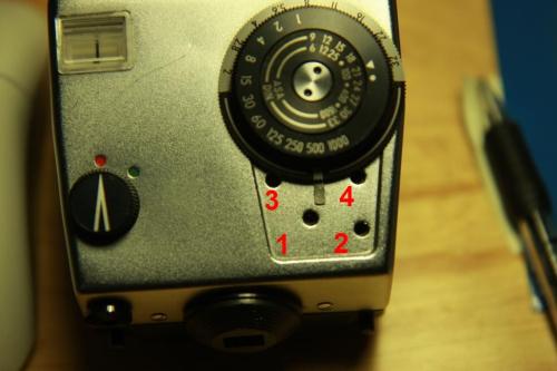
TTL metered prism calibration
The Pentacon Six TTL metered prism measures the amount of light entering through the lens using a CdS photoresistor. First I’m going to talk a little bit about how it works. If you don’t want to know how it works, or getting more confused as you read on, you can still get the job done by just skipping the next three paragraphs and jump to the one after those.
Cadmium sulfide, or CdS, is a semiconductor that is often used for making light detectors. They are called photoresistor because of its variable resistive property to light: the resistance decreases as more light (more photons) hitting its surface. The reading is realized by a galvanometer – an ammeter that measures current. If you understand Kirchhoff’s circuit laws, having only one resistor (even though it’s a variable one) in a circuit loop is not enough to establish a current measurement because no electrons are branched off throughout the entire circuit. We need at least a simple current divider circuit to achieve that.

In our TTL meter prism, we have a set of two adjustable resistors which are serial to each other, but parallel to the photoresistor. They are labelled 3 and 4 in the picture above. R3 has a large resistance for quick ball-park adjustments while R4 has a small resistance for fine tuning. This set of resistors is often called a “shunt” in our electronics jargon. The problem is that the current measurement (Io) is not exactly linear vs. the resistance of the photoresistor (Rx), as shown in our current divider formula:
Io = I_input * Rx/(Rx + R3 + R4)
We can see that linearity occurs only when R3 + R4 ≈ C – Rx, where C is a constant larger than Rx. Practically, it means that the shunt needs to be readjusted accordingly if the photoresistance is very high (dark) or low (bright), in order to maintain (approximate) linearity. The purpose of having an adjustable shunt is exactly for this: to facilitate measurement in very low or high-light situations. Unfortunately, if you screw up the linearity by turning these resistors carelessly as I did, you’ll have a hard time readjusting it.
The next comes to offset adjustments. Offset adjustments are sometimes necessary to compensate variations such as temperature and aging of the coil inside the galvanometer. This is realized by the use of adjustable resistors serial to the photoresistor. They are R1 (large) and R2 (small). The offset is not exactly linear either as we now have this:
Io = I_input * (Rx + R1 +R2)/(Rx +R1 + R2 + R3 + R4)
It’s OK as long as R1 and R2 are relatively small.
In order to calibrate your prism, first you need a reliable reference – a good light meter, a digital camera, or even a sunny day using the Sunny f16 Rule. You’ll need a gray card as target as well. If you don’t have one handy, asphalt concrete or healthy green grass are good approximation. This is how I did:
- Peel off the leatherette on the top of the prism as pictured above.
- On a sunny day, use a reliable meter (I use my Canon 40D )to target the gray card at f5.6, ISO125 and Av mode, and get the shutter speed reading. It should give you around 1/1000s shutter speed using Sunny f16 Rule.
- Then use your Pentacon Six with the TTL metered prism and your favourite lens (I use my 80mm f2.8 Biometar) and follow the same setting – set the lens to f5.6 and set the prism meter dial to ASA125. Turn the power of the prism on. Press and hold the stop-down lever of the lens. Adjust the shutter speed ring of the meter dial until the needle points to the centre of the scale. Check if the recommended shutter speed aligns with the reading from the reference. If not, adjust knob 1 or 2 pictured above using a small screwdriver. Attention: Make sure the screwdriver is not touching any knobs when you take a reading, as the conductance of the screwdriver intervenes with the meter.
- Then repeat Steps 2 and 3, but this time with f16 (if your lens can go to f22, go for it). You should get something around 1/125s (or 1/60s for f22) this time. If the TTL meter is linear, it should align with your reference this time around and no adjustment is needed. If so, congratulations and you’re done with the calibration. If not, read on – we have to play around with knobs 3 and 4 as well as 1 and 2.
- First check how much knob 3 can trun. Mine can turn about 240°, which is from 12 o’clock to 8 o’clock.
- Turn knob 3 all the way counterclockwise. Reapt Steps 3 and 4. If the reading does not closely align to the reference at the end of Step 4, turn knob 3 by 30° clockwise and do again. Repeat until you get something close to the reference in Step 4. My “sweetspot” for daylight use is happened to be in the middle, which is 4 o’clock position. Yours can be different.
- Use knob 4 for fine-tuning if necessary, again by repeating Steps 5 and 6 – where states turning knob 3, turn knob 4 instead.

Very helpful. Thanks.
Thank you, you literally saved my prism, I could not figure out how to tune it .